Setting up our Circuitpython toolchain
Step 1: Setting up the IDE
There are many IDEs that we can use to program CircuitPython robot, we can even just use a text editor.
However we'll be using one called "Mu Editor". So let's begin by downloading it.
Download
You can also get it from the Mu website, https://codewith.mu/en/
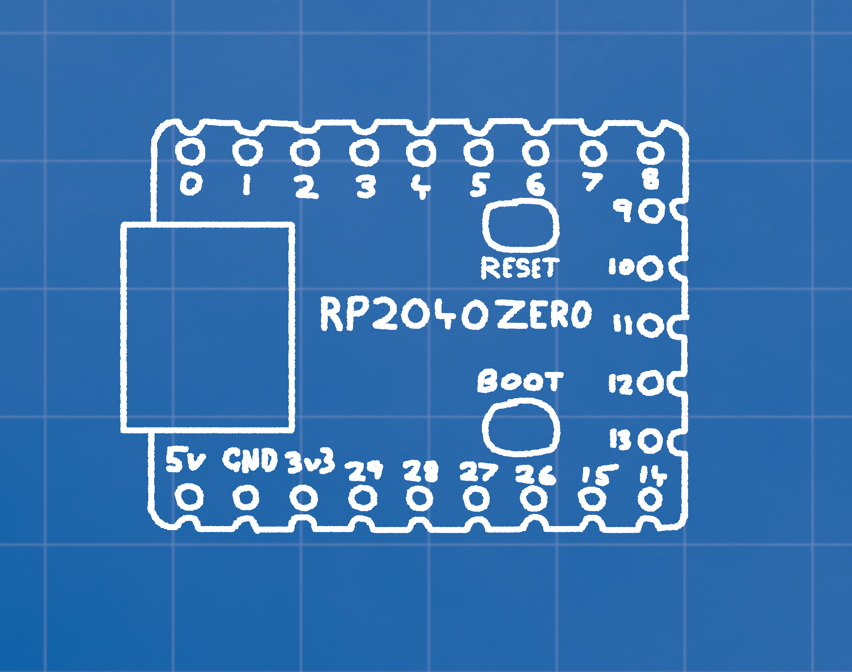
Step 2: Install Circuitpython on board
- Download the CircuitPython firmware UF2 file for the RP2040 Zero here.
- Connect your RP2040 Zero to your computer using a USB cable.
- Hold down the BOOT button, press and release the RST button.
- A new USB drive appears in your file explorer called RPI-RP2.
- Drag the downloaded CircuitPython firmware file into the RPI-RP2 drive.
- The firmware will install, and after a moment, the drive should be called CIRCUITPY.
- Open the drive and examine the different files in there. The "code.py" file is our main file, but we won't open it here.
- Open the MU Editor, and we can start coding!
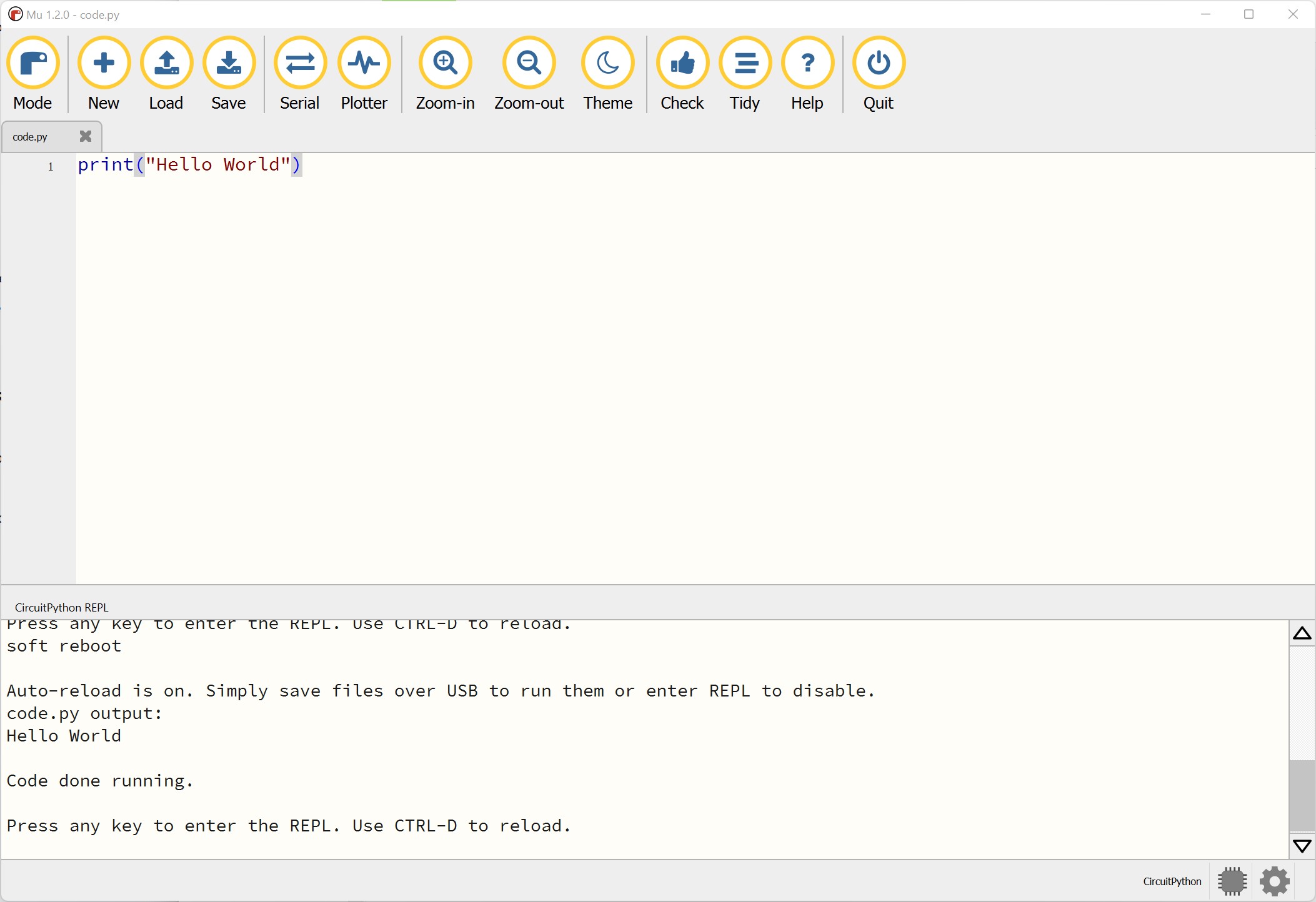
The MU IDE
Step 1: Open the CIRCUITPY/code.py file
When your device is plugged into your computer, you should be able to find the CIRCUITPY drive in your list of drives. Open the code.py file on that drive using the "Load" button.
Step 2: Open the Serial Monitor
To get messages back from your device, and to read errors, press the "Serial" button nd make sure you have the "CircuitPython REPL" window open at the bottom.
Step 3: Hello World
Your code is only updated on your device when you press "Save". If you write the code
print("Hello World") and then save, yuou should see the message appear in the
Serial monitor.
Step 4: Code all the things!
From here you can start to write code, if you need a refresher on basic python code, go to the online lessons here.
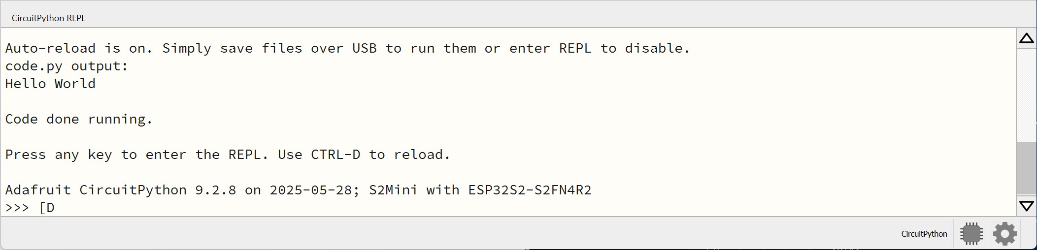
Note: Common Problems
If you see the ">>>" at the bottom of your serial monitor, and your code isn't running, that's because you've accidentally put the monitor into a special mode that lets you write code directly into serial. In this case your saved code won't run. To escape this mode, select the serial monitor, press "enter/return" a few times, and press CTRL-D.
Driving a Motor
Step 1: Wiring
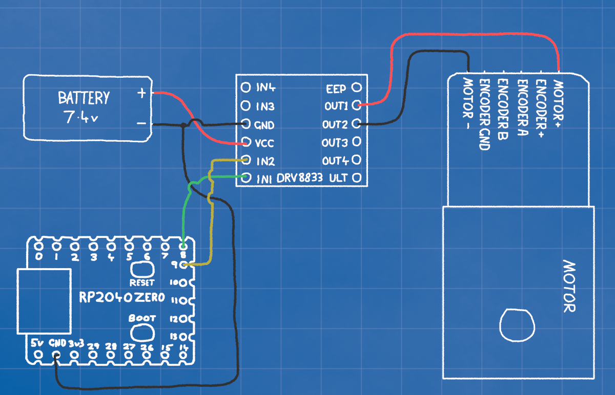
!!DO NOT CONNECT POSITIVE BATTERY DIRECTLY TO THE MICROCONTROLLER!!
The connections on the RP2040 all use 3.3v (3v3), which is far too little to drive the motors. It can drive a motor DRIVER though. The motor driver lets us control the larger voltage from the battery to the motor.
MOTOR+ (red) ------------- DRIVER OUT1
MOTOR- (black) ----------- DRIVER OUT2
RP2040 GP9 --------------- DRIVER IN2
RP2040 GP8 --------------- DRIVER IN1
BATTERY+ (red) ----------- DRIVER VCC
BATTERY- (black) --------- DRIVER GND --------- RP2040 GND
The driver is powered by the battery, but the microcontroller with be powered by the USB. It's very important that the positive battery voltage is never connected directly to the RP2040 as that will immediately release the magic smoke.
The GND on the RP2040, driver, and battery must all be connected though. The GND is 0 volts, and is used as a reference to make sure 0 is the same on every device.
Step 2: Coding
We control the motor driver by switching which of the OUT1 and OUT2 connections is the positive and negative. When one is "high" and the other "low", the motor spins one way. If we switch which is high and low the motor will spin the other way.
To set OUT1 to max voltage, we set IN1 to 3.3v, the same for OUT2 and IN2. We can get finer control by using PWM controls, which turn the pins high and low quickly enough that it simulates voltages in between 0v and 3.3v
import board
import pwmio
import time

motorIN1 = pwmio.PWMOut(board.GP8, frequency=1000, duty_cycle=0)
motorIN2 = pwmio.PWMOut(board.GP9, frequency=1000, duty_cycle=0)


# DRIVE FORWARD
motorIN1.duty_cycle = 65535 # This is the maximum value
motorIN2.duty_cycle = 0     # This is the minimum value
time.sleep(1)

# DRIVE BACKWARD
motorIN1.duty_cycle = 0
motorIN2.duty_cycle = 65535
time.sleep(1)

# STOP
motorIN1.duty_cycle = 0
motorIN2.duty_cycle = 0
Step 3: Making it easier
This works, but takes a lot of typing each time, and is a little hard to read. On the right we can see a function which lets us drive the motor with a single command, and set the speed with a number from -100 to 100.
import board
import board
import pwmio
import time

# Initialize motor PWM pins
motorIN1 = pwmio.PWMOut(board.GP8, frequency=1000, duty_cycle=0)
motorIN2 = pwmio.PWMOut(board.GP9, frequency=1000, duty_cycle=0)

def motor(power):
    # Make sure power is never greater than 100 or less than -100
    if power > 100:
        power = 100
    elif power < -100:
        power = -100

    # Convert 0-100 value, to 0 to 65535
    duty = abs(power) * 65535 // 100

    # Apply power to the correct motor pin
    if power > 0:
        motorIN1.duty_cycle = duty
        motorIN2.duty_cycle = 0
    elif power < 0:
        motorIN1.duty_cycle = 0
        motorIN2.duty_cycle = duty
    else:
        motorIN1.duty_cycle = 0
        motorIN2.duty_cycle = 0

# TESTS
motor(100) # FULL FORWARD
time.sleep(3)
motor(-100) # FULL REVERSE
time.sleep(3)

# Start at FULL REVERSE and slowly change from -100 to 100
for i in range(-100, 100):
    motor(i)
    print(i)
    time.sleep(0.1)
Step 4: Making it professional
Finally, to make our final code modular, cleaner, and easier to understand we can offload all out motor code into a new module.
We make a second file called motor.py which we'll import and call from our main
code.py file.
Now all we need to do from the main code is:
Import the module
import motors
Initialize a motor object
left_motor = motor.Motor(board.GP8, board.GP9)
Set the power
left_motor.move(100)
You can also add a second, third, or 20th motor at any time just by initializing another motor.Motor object.
right_motor = motor.Motor(board.GP10, board.GP11)
# code.py
import board
import time
import motor

left_motor = motor.Motor(board.GP8, board.GP9)

# TESTS
left_motor.move(100)   # FULL FORWARD
time.sleep(2)
left_motor.move(-100)  # FULL REVERSE
time.sleep(2)
left_motor.move(0)

# Start at FULL REVERSE and slowly change from -100 to 100
for i in range(-100, 100):
    left_motor.move(i)
    print(i)
    time.sleep(0.1)
Reading the Colour Sensor
Step 1: Wiring
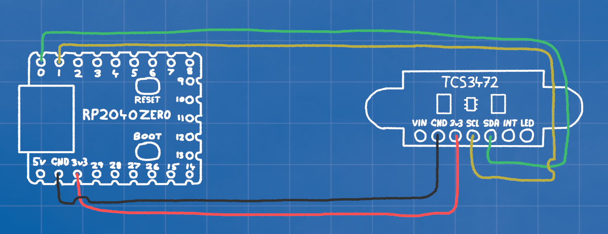
The TCS3472 Colour sensor is a smart device that uses I2C communication. This is a method of communication from one microcontroller to another, using only 2 wires (SCL and SDA).
RP2040 3v3 --------------- SENSOR 3v3
RP2040 GND --------------- SENSOR GND
RP2040 GP0 --------------- SENSOR SDA
RP2040 GP1 --------------- SENSOR SCL
So we need to connect power (3v3 and GND), and the two GPIO pins for communication.
We don't use VIN, this is for if we are using more than 3v3, the sensor has its own voltage regulator on board.
The INT pin on the sensor is an INTERRUPT. It flips on and off when theres new data to be read.
The LED pin on the sensor can be connected to a GPIO and switched high and low to turn it off and on. It's on by default.
Step 2: Coding
The minimal code to communicate with the colour sensor is a bit more in depth than the motor. We need to write and read registers, send bytes back and forth to turn it on, tell it what speed to work at, and how sensitive to be.
Since it's quite a lot we'll begin by putting it in a separate file. The code here includes the minimum needed to set up and read the colour sensor.
init_sensor() sends 4 messages to the sensor. The first tells it to turn on, the
second tells it to turn on its RGB colour sensing.
The "Integration Time" controls how long the sensor will collect data before collating it into a message for you. Since we want to read hundreds of times a second we set it low.
Finally we set the "gain" quite high, this amplifies the signal, which is necessary since our fast integration time leaves the sensor with low sentivity.
If we only had to check the colour every half a second or so, we could get a much more sensitive result by setting a high integration time, and low gain.
# color.py

import time

TCS_ADDR = 0x29
COMMAND_BIT = 0x80

def i2c_locked(i2c, func, *args, **kwargs):
    """Wraps I2C operations with lock acquisition and release."""
    while not i2c.try_lock():
        pass
    try:
        return func(*args, **kwargs)
    finally:
        i2c.unlock()

def write_register(i2c, addr, reg, value):
    """Writes a byte to a register."""
    i2c_locked(i2c, i2c.writeto, addr, bytes([COMMAND_BIT | reg, value]))

def read_register(i2c, addr, reg, length):
    """Reads multiple bytes from a register."""
    result = bytearray(length)

    def transfer():
        i2c.writeto(addr, bytes([COMMAND_BIT | reg]))
        i2c.readfrom_into(addr, result)
        return result

    return i2c_locked(i2c, transfer)

def init_sensor(i2c):
    time.sleep(0.01)
    write_register(i2c, TCS_ADDR, 0x00, 0x01)  # Enable (POWER ON)
    time.sleep(0.01)
    write_register(i2c, TCS_ADDR, 0x00, 0x03)  # Enable (COLOR SENSING ON)
    write_register(i2c, TCS_ADDR, 0x01, 0xFF)  # Integration time 0xFF=2.4ms 0xF0=38.4ms 0x00=614.4ms
    write_register(i2c, TCS_ADDR, 0x0F, 0x03)  # Gain 0x00=1x, 0x01=4x 0.02=16x, 0x03=60x

def read_rgbc(i2c):
    data = read_register(i2c, TCS_ADDR, 0x14, 8)
    c = data[1] << 8 | data[0]
    r = data[3] << 8 | data[2]
    g = data[5] << 8 | data[4]
    b = data[7] << 8 | data[6]
    return r, g, b, c
Step 3: code.py
Finally, this is how we call our color.py code from our main code, initialise and read the sensor.
We use the busio library to handle our i2c. We initialise the connection by telling
it which pins we're using for SCL and SDA, and how fast to communicate.
We then pass on that connection to initialize the sensor using
color.init_sensor(i2c)
The whenever we read color.read_rgbc(i2c) it will give us an array with the
[red, green, blue, color], with the color being the total light reflected, rather
than just a single color.
# code.py

import busio
import time
import board
import color

i2c = busio.I2C(scl=board.GP1, sda=board.GP0, frequency=1_000_000)
color.init_sensor(i2c)

while True:
    value = color.read_rgbc(i2c)
    print(value)
    time.sleep(0.1)
Step 4: How to use it?
To take these numbers and use them effectively, we need to break out the different colour channels.
To the right is an example of how we might take the total colour from the result, and then use it to decide whether to turn or not.
value = color.read_rgbc(i2c) # Read the sensor [r,g,b,c]
# Extract each of the color values from the array
r = value[0] # red
g = value[1] # green
b = value[2] # blue
c = value[3] # all colors

if c > 30: # If the c value is greater than 30
    # Turn Right
    left_motor.move(50)
    left_motor.move(-50)
else:
    # Go Straight
    left_motor.move(50)
    left_motor.move(50)
Reading MORE Colour Sensors
Step 1: Wiring
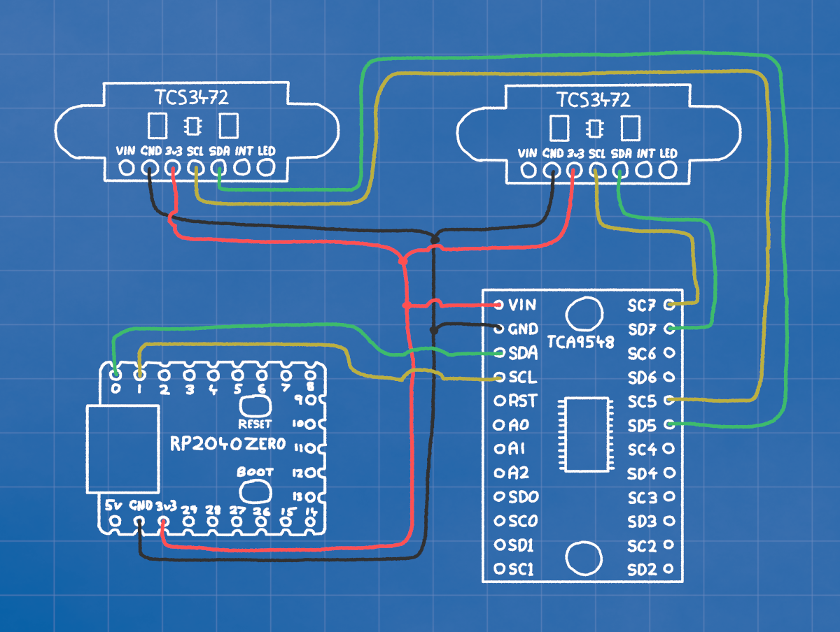
Although you can connect many devices to the SCL SDA pins, each device must have a different address. This is a problem because every colour sensor has the same address.
If we just connected all our devices to the same SCA and SDA lines, they would both try to respond at the same time to every message addressed to them
So we use a MULTIPLEXER. This lets us have 8 different I2C channels, with only one active at once. So with the connections in the picture, we'd switch to channel 5 to talk to the left sensor, and channel 7 to talk to the right.
RP2040 3v3 -- MUXER 3v3 -- SENSOR 1 3v3 -- SENSOR 2 3v3
RP2040 GND -- MUXER GND -- SENSOR 1 GND -- SENSOR 2 GND
RP2040 GP0 -- MUXER SDA
RP2040 GP1 -- MUXER SCL
MUXER SD5 --- SENSOR 1 SDA
MUXER SC5 --- SENSOR 1 SCL
MUXER SD7 --- SENSOR 2 SDA
MUXER SC7 --- SENSOR 2 SCL
Using this method, we can connect up to 8 colour sensors.
Step 2: Coding
Create a new module and paste the code on the right in there.
It's similar to the colour sensor code, we pass the select_channel() function the
i2c, and a number for which channel (0-7) we want to talk through.
It sends a single message over the I2C bus, to the multiplexers address, telling it which channel to open.
# muxer.py

TCA_ADDR = 0x70

def i2c_locked(i2c, func, *args, **kwargs):
    """Wraps I2C operations with lock acquisition and release."""
    while not i2c.try_lock():
        pass
    try:
        return func(*args, **kwargs)
    finally:
        i2c.unlock()

def select_channel(i2c, channel):
    """Selects the TCA9548A multiplexer channel."""
    if not 0 <= channel <= 7:
        raise ValueError("Channel must be 0-7")
    i2c_locked(i2c, i2c.writeto, TCA_ADDR, bytes([1 << channel]))
Step 3: code.py
So in our main code we just import the muxer module, and make sure we switch to the correct channel before sending any messages.
We only need to keep one colour sensor object, but we do need to make sure we send the initialization message on each channel.
# code.py

import busio
import time
import board
import color
import muxer

i2c = busio.I2C(scl=board.GP1, sda=board.GP0, frequency=1_000_000)

# select channel 5
muxer.select_channel(i2c, 5)
# init sensor on channel 5
color.init_sensor(i2c)

# select channel 7
muxer.select_channel(i2c, 7)
#init sensor on channel 7
color.init_sensor(i2c)

while True:
    # select channel 5
    muxer.select_channel(i2c, 5)
    # read the values on channel 5
    value5 = color.read_rgbc(i2c)

    # select channel 7
    muxer.select_channel(i2c, 7)
    # read the values on channel 7
    value7 = color.read_rgbc(i2c)

    # print both sets of readings
    print(value5, value7)

    time.sleep(0.1)
Using the OLED Display
Step 1: Wiring
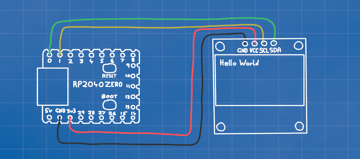
The OLED display also communicates using I2C, so all we need to do is connect the power (3v3 and GND), and the I2C lines (SDA and SCL).
RP2040 3v3 ------- OLED 3v3
RP2040 GND ------- OLED GND
RP2040 GP0 ------- OLED SDA
RP2040 GP1 ------- OLED SCL
Step 2: Coding
The code for the OLED is a little more complicated that what we want to code for ourselves, so we'll download a library and place it in out CIRCUITPY/lib folder.
We initialize the display with display = adafruit_ssd1306.SSD1306_I2C(128, 32, i2c).
We colour the entire screen either black (off) or blue/white (on) with
display.fill(0) for off, or 1 for on.
We write text with display.text(text, x, y, color).
Finally, before anythin will actually appear on the screen, we send it using
display.show().
import board
import time
import busio
import adafruit_ssd1306

i2c = busio.I2C(scl=board.GP1, sda=board.GP0, frequency=1_000_000)
display = adafruit_ssd1306.SSD1306_I2C(128, 32, i2c)


display.fill(0) # Fill the screen with BLACK
# Print Hello world at the top left in COLOR
display.text("Hello World", 0, 0, 1)
display.show() # Send the update to the screen
time.sleep(2)


display.fill(1)# Fille the screen with COLOR
display.show() # Send the update to the screen
time.sleep(2)

# Print Hello world at x:10, y:20 in BLACK
display.text("Hello World", 10, 20, 0)
display.show() # Send the update to the screen
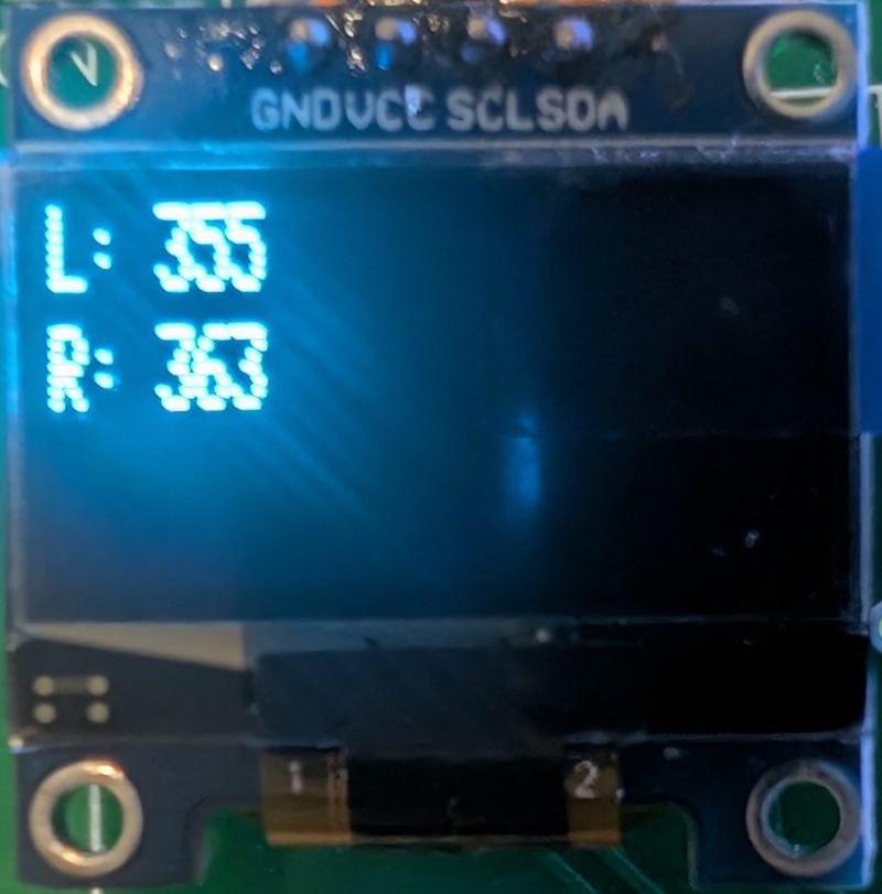
Step 3: How to use it?
One of the main things we'll use the screen for is getting feedback on what the sensors are seeing, or what the robot is doing.
So when the robot is following a line, we might do something like the code on the right so that we can see the sensor colours in real time.
import board
import time
import busio
import adafruit_ssd1306
import color
import muxer

i2c = busio.I2C(scl=board.GP1, sda=board.GP0, frequency=1_000_000)
display = adafruit_ssd1306.SSD1306_I2C(128, 32, i2c)

# initialize two colour sensors
muxer.select_channel(i2c, 0)
color.init_sensor(i2c)
muxer.select_channel(i2c, 1)
color.init_sensor(i2c)


while True:
    # Read the colour channel from both colour sensors
    muxer.select_channel(i2c, 0)
    value0 = color.read_rgbc(i2c)[3]
    muxer.select_channel(i2c, 1)
    value1 = color.read_rgbc(i2c)[3]

    # Print the results on the display
    display.fill(0)
    display.text("L: " + str(value0), 0, 0, 1)
    display.text("R: " + str(value1), 0, 10, 1)
    display.show()
    time.sleep(0.1)
RGB LED (Neopixel)
Step 1: Wiring
The RGB LED has its own little microcontroller we can talk to and set each of the three LEDs inside. We only need power and a single data connection.
RP2040 3v3 ------- RGB 5v
RP2040 GND ------- RGB GND
RP2040 GP29 ------ RGB DIN
Even though the RGB LED says it wants 5v, we give it 3v3. It's designed for 5v, but if we give it 5v power then the data sent to it using a 3v3 signal from GP29 won't be recognized.
Many of these leds can be connected in a string, with each one passing the messages along to the next. We'll just be using one in the examples here.
Step 2: Coding
Once again we'll be using a library to handle all the bits and bytes under the hood, so we only have to worry about setting colours.
We only need to initialize the pixel with
pixel = neopixel.NeoPixel(board.GP29, 1, brightness=0.2).
The "1" is the number of pixels we have, and we CAN set the brightness up to 1.0 but it's quite bright.
Then we just need to tell the pixel what colour to be, we talk to
pixel[0] = (red,green,blue) because
it's the only one we have. The numbers for each colour go from minimum 0, to maximum 255.
import board
import time
import neopixel

pixel = neopixel.NeoPixel(board.GP29, 1, brightness=0.2)

while True:
    pixel[0] = (255, 0, 0)  # Red
    time.sleep(1)
    pixel[0] = (0, 255, 0)  # Green
    time.sleep(1)
    pixel[0] = (0, 0, 255)  # Blue
    time.sleep(1)
Step 3: Make some pretty effects
This example has three loops, each one fades from one primary colour to the next.
We increase one LEDs brightness by assigning it i, which counts from 0-255
We decrease another LEDs brightness by making it 255-i so it begins at max, and
counts
down to zero as i becomes higher.
import board
import time
import neopixel

pixel = neopixel.NeoPixel(board.GP29, 1, brightness=0.2)

while True:
    # Fade Red->Green
    for i in range(256):
        pixel[0] = (255-i, i, 0)

    # Fade Green->Blue
    for i in range(256):
        pixel[0] = (0, 255-i, i)

    # Fade Blue->Red
    for i in range(256):
        pixel[0] = (i, 0, 255-i)
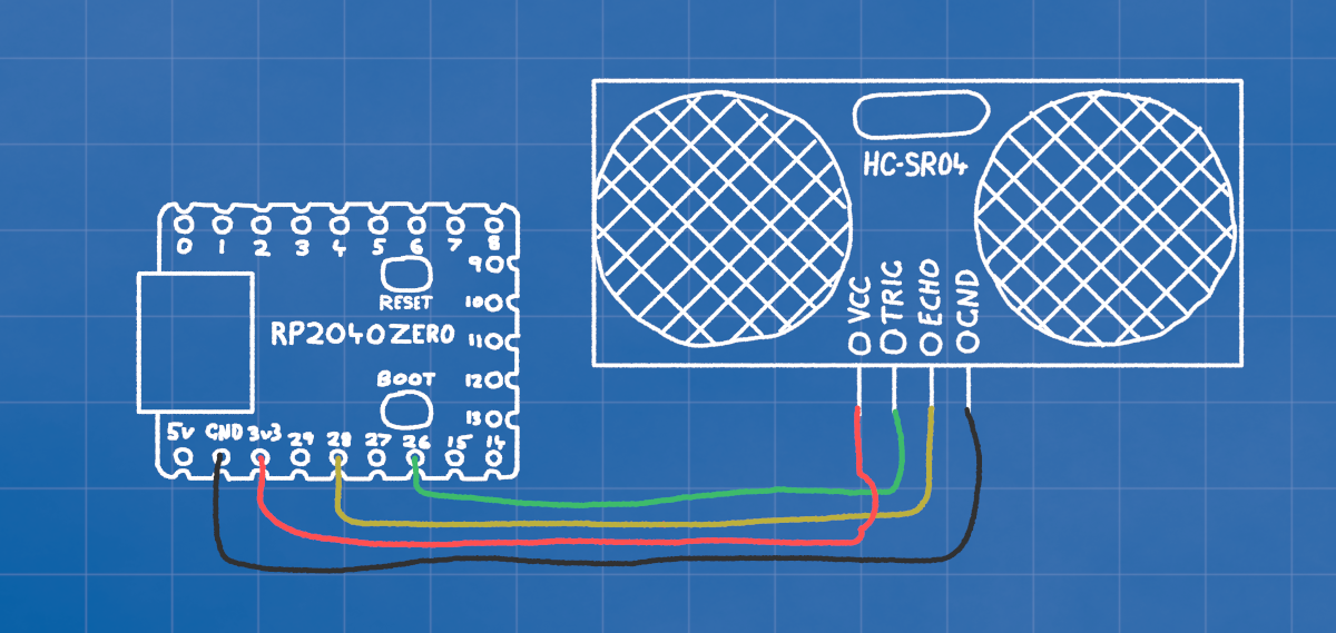
Sonar HC-SR04
Step 1: Wiring
The HC-SR04 sonar sends out a little pulse when we turn the TRIG pin on and off. When the sound bounces back from something the ECHO pin will turn on and off. We use the time between the TRIG and the ECHO to determine how far the sound got before bouncing back from an object.
RP2040 3v3 ------- SONAR 5v
RP2040 GND ------- SONAR GND
RP2040 GP26 ------ SONAR TRIG
RP2040 GP28 ------ SONAR ECHO
Step 2: Coding
We'll use a library to handle sending and listening for the pulses. Put this module in your CIRCUITPY/lib folder.
Note the timeout=0.005, this is important as it tells the code how long to wait for
an ECHO. If we don't have that, our code could be blocked for quite a lot of time if the only
obstacles are a long way away.
Even though all we really need is to get the distance with sonar.distance, when no
echo is received in time an error will occur that will stop your code from running.
With our try-except block, any errors will just run whatever is in the
except part. In this case, nothing.
import board
import adafruit_hcsr04

# Initialize the sonar device
sonar = adafruit_hcsr04.HCSR04(trigger_pin=board.GP26, echo_pin=board.GP28, timeout=0.005)

while True:
    distance = 99

    # The try-except block catches errors that
    # occur when no signal returns in time
    try:
        distance = sonar.distance
        print(distance)
    except RuntimeError as e:
        pass
Step 3: Clean it up a bit
To tidy up our main loop, we can move all that to a function so the main loop just needs
get_distance().
If your code is getting quite long, you might even take functions like this and put them in your own module to keep your main code easy to read.
import board
import time
import adafruit_hcsr04

# Initialize the sonar device
sonar = adafruit_hcsr04.HCSR04(trigger_pin=board.GP26, echo_pin=board.GP28, timeout=0.005)

def get_distance():
    distance = 99
    try:
        distance = sonar.distance
    except RuntimeError as e:
        pass
    return distance

while True:
    print(get_distance())
    time.sleep(0.1)
Receiver
Step 1: Coding
Create a new file called remote.py and add the code to the right.
# remote.py

import board
import busio

START_BYTE = 0xAA
END_BYTE = 0xBB
PACKET_LENGTH = 8

# Calibration values
LEFT_MIN = 0
LEFT_MID = 131
LEFT_MAX = 203
RIGHT_MIN = 51
RIGHT_MID = 120
RIGHT_MAX = 255

class ThumbInput:
    def __init__(self, tx=board.GP0, rx=board.GP1, baudrate=115200):
        self.uart = busio.UART(tx=tx, rx=rx, baudrate=baudrate, timeout=0.1)
        self.buffer = bytearray()

    def read(self):
        """Returns (left_percent, right_percent) in range [-100, 100], or None if packet incomplete."""
        data = self.uart.read(1)

        if data:
            byte = data[0]
            self.buffer.append(byte)

            if len(self.buffer) > PACKET_LENGTH:
                self.buffer = self.buffer[-PACKET_LENGTH:]

            if len(self.buffer) == PACKET_LENGTH and self.buffer[0] == START_BYTE and self.buffer[-1] == END_BYTE:
                payload = self.buffer[1:7]
                self.buffer = bytearray()
                left_raw = payload[1]
                right_raw = payload[3]

                left = self._map_thumbstick(left_raw, LEFT_MIN, LEFT_MID, LEFT_MAX)
                right = self._map_thumbstick(right_raw, RIGHT_MIN, RIGHT_MID, RIGHT_MAX)

                return (int(left), int(right))

        return None

    def _map_thumbstick(self, x, min_val, mid_val, max_val):
        if x < mid_val:
            return (x - mid_val) / (mid_val - min_val) * 100
        else:
            return (x - mid_val) / (max_val - mid_val) * 100
Step 2: Using the recieved signal
Import just the ThumbInput part of the library.
Initialize the receiver with receiver = ThumbInput()
Create a new loop as this won't work nicely with any i2c, this loop should be placed after the motors are created, and before the i2c is initialized.
from remote import ThumbInput

receiver = ThumbInput()

while True:
    result = receiver.read()
    if result:
        left_motor.move(result[0])
        right_motor.move(result[1])
        #print("Left:", result[0], "Right:", result[1])
    time.sleep(0.001)
PID
Step 1: Coding
Up until now we've been using an algorithm known as "bang-bang" to track the line.
If the left sensor sees something, we take a single action, turn left.
Else if the right sensor sees something, we take a single action, gurn right.
Else go straight.
This works well, but it can be a bit jerky.
Bang-Bang Algorithm
Bang-Bang Controller Parameters
left_color: 0
right_color: 0
Step 2: Use a PID algorithm
A PID algorithm on the other hand tries to always keep the robot exactly on the line.
First we have to change our two colour values, left_color and
right_color into a single error value.
right_color - left_color = error
Now if we are on the line our error should be 0, with ot becoming positive if we move one way, and negative if we move the other.
Try adjusting the Kp value to control how aggressively the robot will attempt to
drive towards the line.
PID Algorithm
PID Controller Parameters
Error (right_color-left_color): 0
Step 3: The Code
The pid.py library is simple, we initialize it with a P, I, and
D.
These stand for Proportional, Integral, and Derivative
The P value controls how aggressively proportional the final result will be, if we
set it too high, the output will be too high and the robot will adjust too hard. If we set it
too low, the robot will be too lazy about tracking the line and may not turn fast enough to stay
on it.
# pid.py

class PIDController:
    def __init__(self, kp, ki, kd):
        self.kp = kp
        self.ki = ki
        self.kd = kd

        self.integral = 0
        self.last_error = 0

    def compute(self, error):
        self.integral += error
        derivative = error - self.last_error
        self.last_error = error

        output = (self.kp * error) + (self.ki * self.integral) + (self.kd * derivative)
        return output
# code.py

import pid

linePID = pid.PIDController(kp=1.0, ki=0.0, kd=0.0)

while True:
    error = right_color - left_color  # Calculate the error
    output = linePID.compute(error)
    # Use the output to adjust the motors
    print(error, output)